3 min to read
ESP12 Based Home Automation
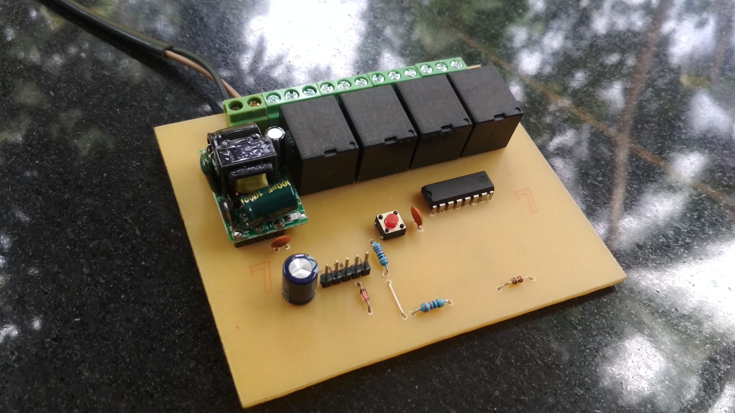
This is an ESP12 based home automation project. The project uses a web interface to control the loads. With help of WiFi, we can control the relays to turn on or off.
Components Required
- R1- 10K
- R2- 1K
- R3- 4.7K
- K1, K2, K3 & K4 – 5V Relay
- C1-100nF (0.1uF)
- C2- 47uF
- C3- 100nF (0.1uF)
- D1- 1N4148
- U1- ULN2003
- U2- AC-DC 5V 700mA 3.5W Power Supply
- U3- AMS1117-3.3 SOT89
- SW- 6x6x6mm Push Button
- J1, J2, J3 & J4- 3 pin Screw Terminal Block
- J5- 5 pin Screw Terminal Block
- H1- 1×5 Male header pin
- MK1- ESP12E
Schematic
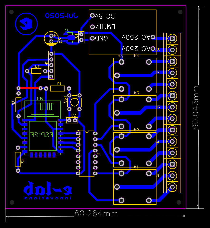
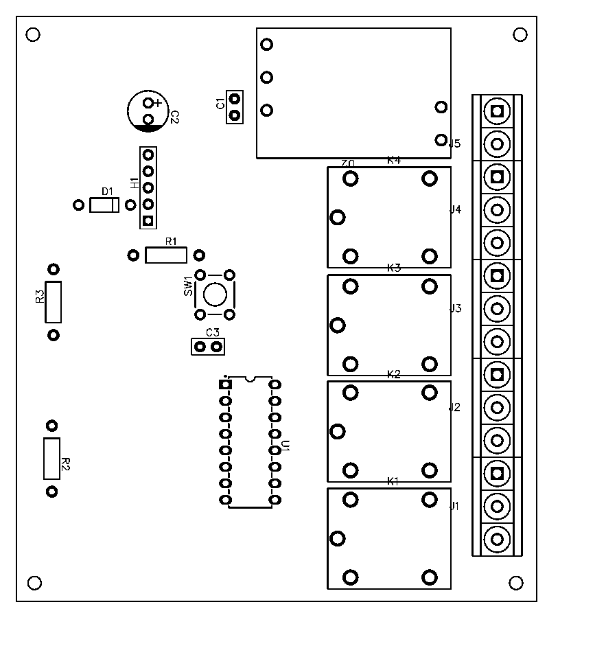
Layout
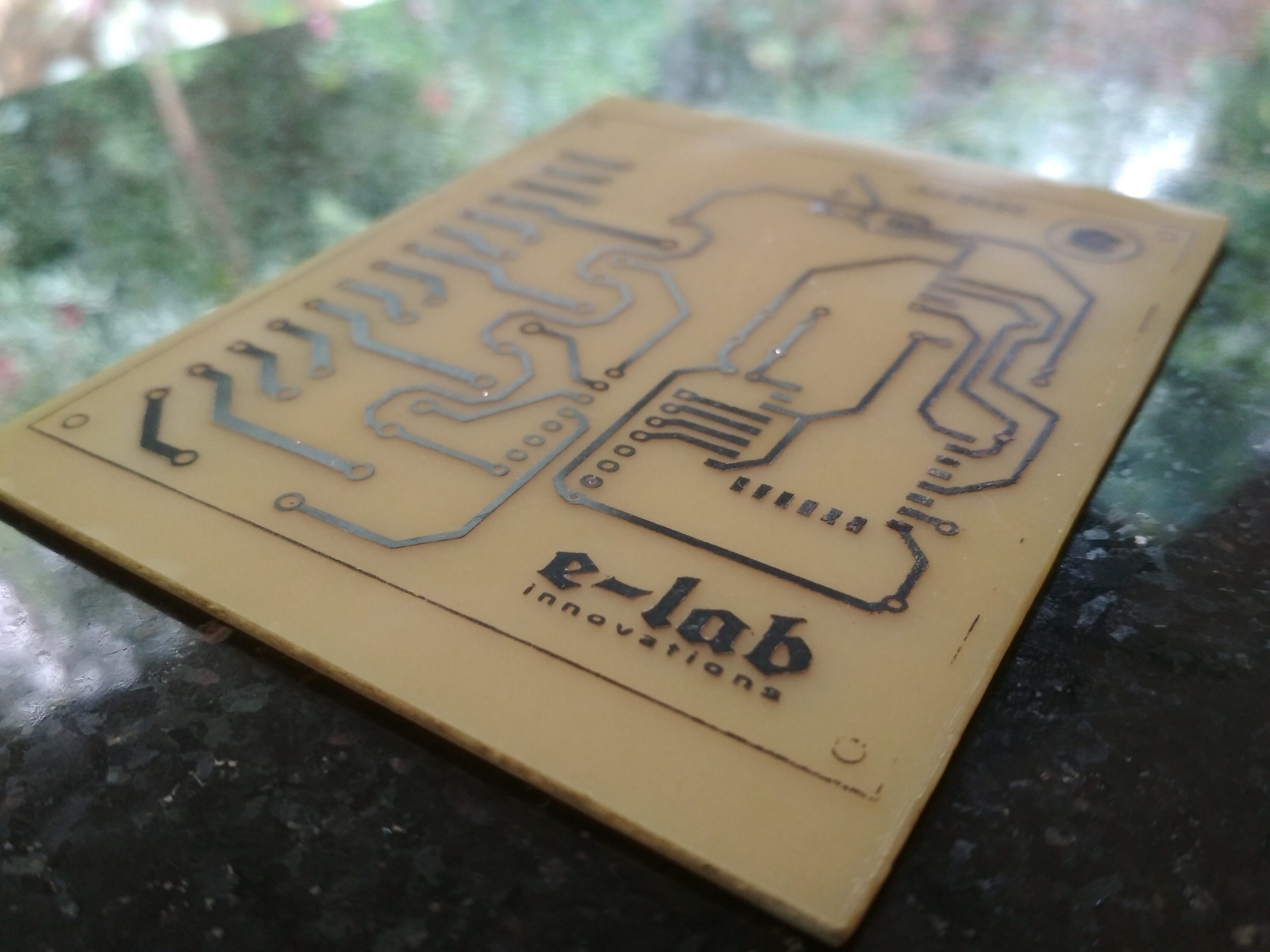
Images
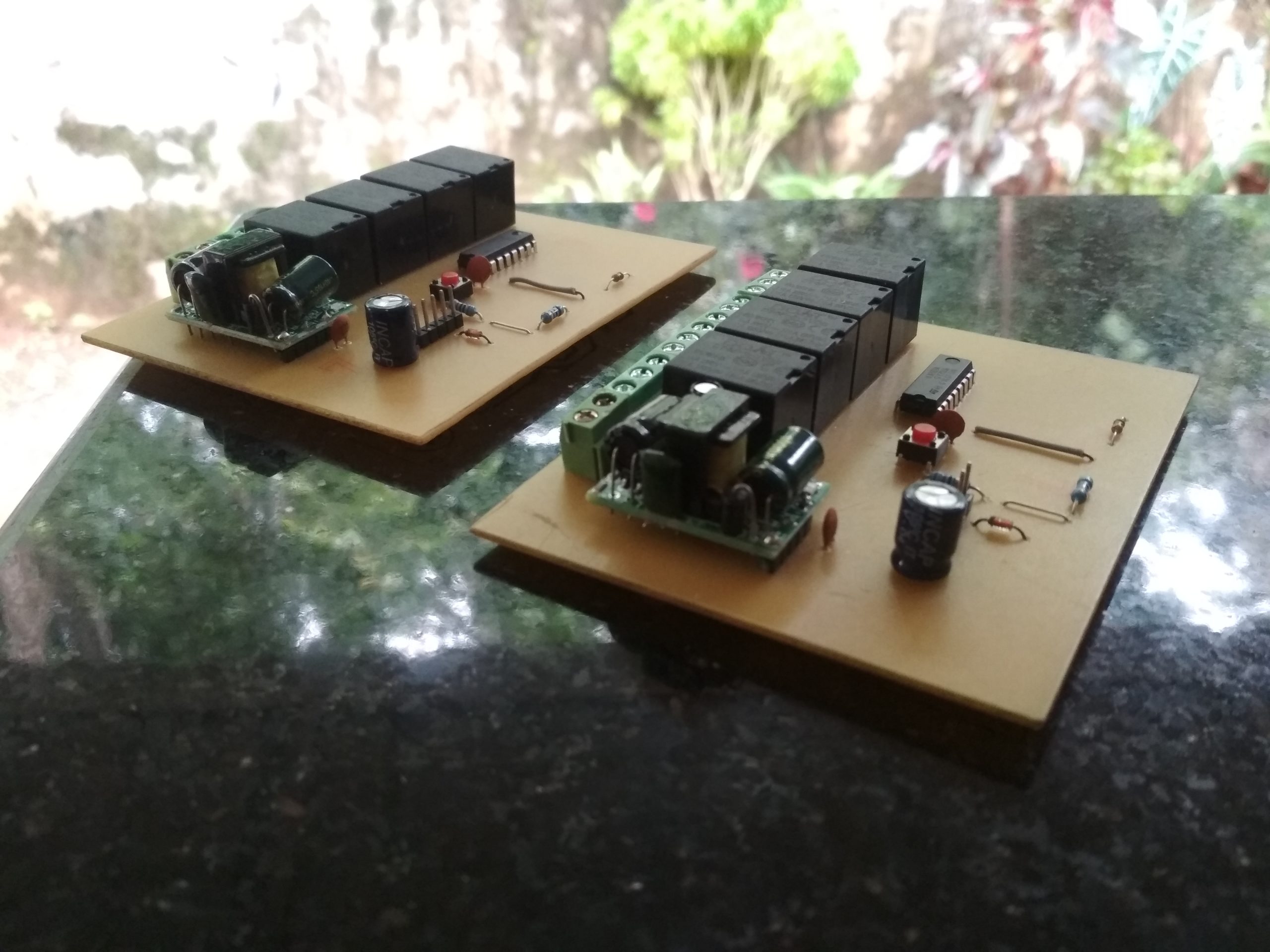

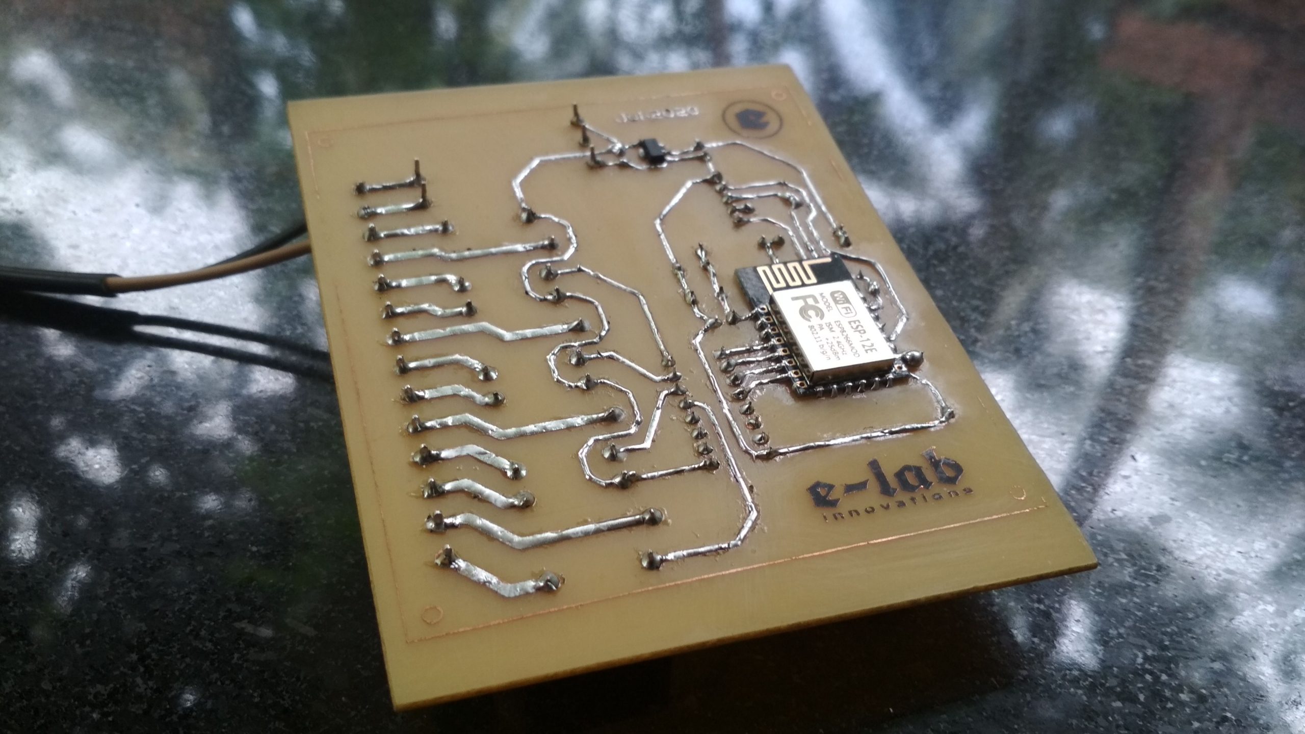
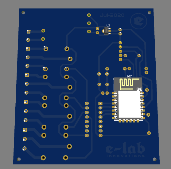
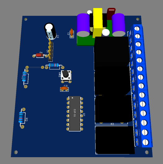
Source Code
https://github.com/e-labInnovations/ESP12-Home-Automation
Instructions
- Download the necessary files (Schematic, Layout and Source Code).
- Create PCB using the given PCB layout.
- Solder the components. Check there is no short on the ESP12 SMD board.
- Connect the USB to TTL converted to the board. You can find a 5pin connector to connect VCC, GND, RX, TX and GPIO0 on the schematic.
- Connect the GPIO0 to GND
- Upload the code using Arduino IDE. Use can choose NodeMCU 1.0 as your board type.
- After uploading, you can see a WiFi access point named ‘Home Automation’ available on your mobile.
- Connect to the access point using the password ‘PASSWORD’.
- After connecting open a web browser like chrome and type the board’s IP address192.168.4.1′.
- After loading the wesite, you can turn on and off the relays available on the board.


Awesome